|
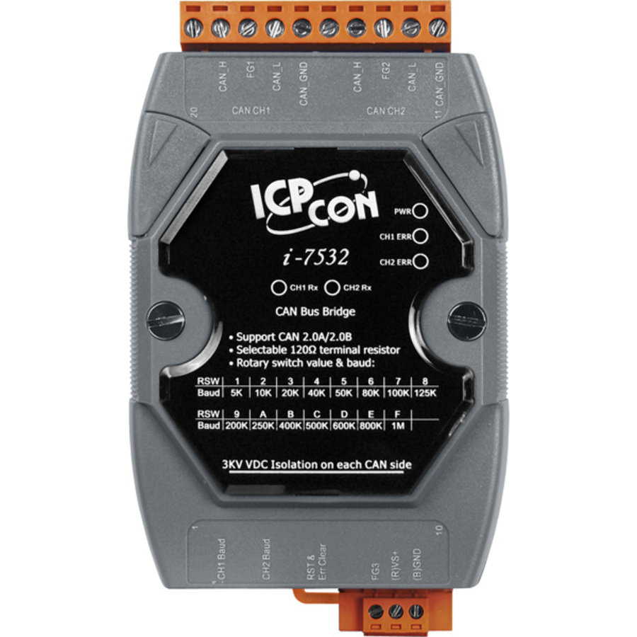
I-7532
|
|
The I-7532 is a CAN bus bridge that can be used to integrate two CAN networks even they implement different CAN baud rate. Compared with the I-7531, the I-7532 offers more than 3 useful features. First, the transmission distance limitation of the CAN bus system on each side of the I-7532 is independent, which means the total CAN network distance can be extended. Second, when some errors (e.g. bit error) happened on one CAN port of the I-7532, the other CAN port of the I-7532 will not be affected and can still work correctly. Last, the baud rate and CAN message filter configuration of these two CAN ports on the I-7532 is able to be tuned following users’ applications. These features mean that users can design their applications more flexible and efficient. |
Request For Quotation
Description

Applications
|
 |
|
|
|
|
|

- 82C250 CAN transceiver
- 2500 VRMS photo coupler isolation on the CAN side
- 3KV galvanic isolation among the power supply and 2 CAN channels
- Support both CAN 2.0A and CAN 2.0B
- Fully compatible with the ISO 11898-2 standard
- Adjustable CAN bus baud rate from 5Kbps to 1Mbps or programmable user-defined baud rate
(For firmware v1.01 or newer) (NEW) - Support CAN bus message acceptance filter configuration
(For firmware v1.01 or newer) (NEW) - Provide I-7532 Utility for CAN bus message acceptance filter and user-defined CAN baud rate etc. configuration easily and quickly
(For firmware v1.01 or newer) (NEW) - Support firmware update via CAN1 of I-7532
(For firmware v1.02 or newer) (NEW) - CAN messages can be forwarded under another identifier
(For firmware v1.03 or newer) (NEW) - Built-in jumper to select 120Ω terminal resistor
- Watchdog inside
- Up to 100 CAN nodes on each channel
- Transmission distance up to 1 km on each CAN port
- Removable terminal block, Mount easily on DIN-rail
- 768 frame buffer for each CAN channel
- The baud of each channel can be different for highly flexibility
- Supports a range of baud rates from 10 kbps ~ 1 Mbps
- Able to configure the CAN baud rate for each channel using a rotary switch
- Extends the CAN transmission distance
Note: We have verified to drive 100 CAN nodes at the same time via one CAN port of I-7532.
| Baud Rate Selection by Rotary Switch |
|
Switch Value
|
0
|
1
|
2
|
3
|
|
Baud [bps]
|
Config
Mode |
5k or User-defined
CAN baud |
10k
|
20k
|
|
Switch Value
|
4
|
5
|
6
|
7
|
|
Baud [bps]
|
40k
|
50k
|
80k
|
100k
|
|
Switch Value
|
8
|
9
|
A
|
B
|
|
Baud [bps]
|
125k
|
200k
|
250k
|
400k
|
|
Switch Value
|
C
|
D
|
E
|
F
|
|
Baud [bps]
|
500k
|
600k
|
800k
|
1000k
|


