I-2533

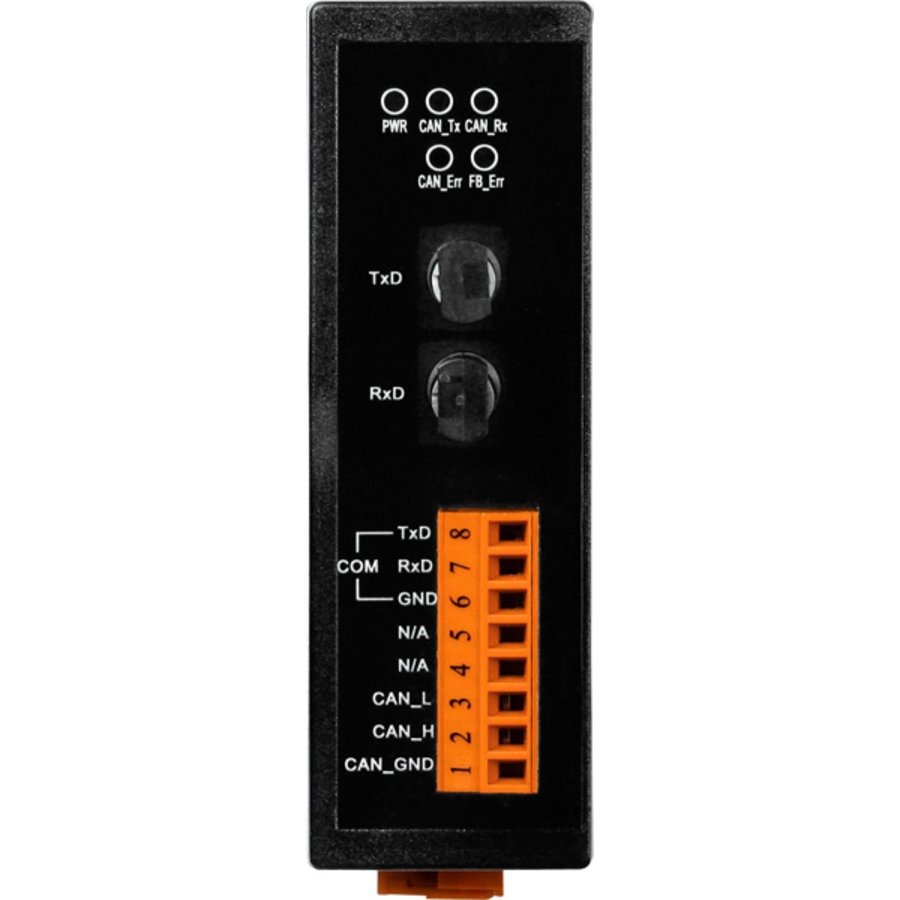
The I-2533 is an intelligent CAN bridge that can be used to establish the connection between two CAN bus systems via fiber optic cable. Similar to the I-2532, the I-2533 can also apply in various CAN-based protocols to convert CAN bus signals to optical signals and reshape the CAN signals. The difference between the I-2532 and I-2533 is the CAN configuration functions and the distance limitation of CAN communication. The I-2533 offers the functions to configure the CAN baud rate and CAN message filters. These are useful when using the I-2533 to link two CAN networks which may have different baud rates. By using the I-2533, the transmission distance limitation of the CAN bus system will not be reduced because of the CAN baud rate, which means that the total network length can be extended. This feature means that users can develop the applications more powerful and flexible with the I-2533.

Request For Quotation

    Description

    Applications

      • Control System
      • Building Automation
      • Factory Automation
      • Distributed data acquisition

    Features

    • 82C250 CAN transceiver
    • 2500 Vrms isolation on the CAN side
    • 3 kv galvanic isolation between the power supply and CAN channel
    • Support both CAN 2.0A and CAN 2.0B specification
    • Fully compatible with the ISO 11898-2 standard
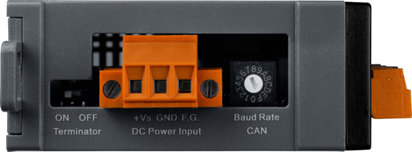
    • Rotary switch for CAN baud rate configuration
    • Built-in switch to select 120Ω terminal resistor
    • Up to 100 CAN nodes on the CAN channel
    • Fiber Port: ST (Multi-mode)
    • Wave Length: 850 nm
    • Transmission distance up to 2 km at any CAN baud rate
    • Provides the 512-record CAN Tx buffer and 512-record CAN Rx buffer
    • Removable terminal block, Mount easily on DIN-rail
    • Allow user-defined baud rate
    • Utility tool for message filter configuration
    • Software utility tool for message filter configuration
    • Broken line detection for fiber cable

    Note: We have verified to drive 100 CAN nodes at the same time via one CAN port of I-2533.


    Network Deployment

    Baud [bit/sec]
    Ideal Fiber Length [m]
    1M
    2000
    800K
    2000
    500K
    2000
    250K
    2000
    125K
    2000
    50K
    2000
    20K
    2000
    10K
    2000


    Hardware Specifications

    CAN Interface
    Connector
    Screwed terminal block (CAN_GND, CAN_L, CAN_H)
    Baud Rate (bps)
    10 k ~ 1 M
    Transmission Distance (m)
    Depend on baud rate
    Terminal Resistor
    Switch for 120Ω terminal resistor
    Isolation
    3000 VDC for DC-to-DC, 2500 Vrms for photo-couple
    Specification
    ISO-11898-2, CAN 2.0A and CAN 2.0B
    Time Delay
    250 us *Note1
    Fiber Interface
    Connector
    ST (Multi-mode)
    Wave Length
    850 nm
    Fiber Cable
    50 / 125 μm , 62.5 / 125 μm, 100 / 140 μm (62.5 / 125μm is recommended)
    Transmission Distance (m)
    2 km max (in 62.5 / 125 μm fiber cable) at any CAN baud rate
    LED
    Round LED
    PWR LED, CAN_Tx LED, CAN_Rx LED, CAN_Err LED, FB_Err LED
    Power
    Power supply
    Unregulated +10 ~ +30 VDC
    Protection
    Power reverse polarity protection, Over-voltage brown-out protection
    Power Consumption
    3 W
    Mechanism
    Installation
    DIN-Rail
    Dimensions
    32.3mm x 77.5mm x 99.0mm (W x L x H)
    Environment
    Operating Temp.
    -25 ~ 75 ℃
    Storage Temp.
    -30 ~ 80 ℃
    Humidity
    10 ~ 90% RH, non-condensing

    Note1:
    The propagation delay depends on the CAN Bus baud rate and the CAN message format. This value has been tested using a CAN baud rate of 1 Mbps, the CAN ID 0x12345678 and 8 bytes of data with a value of 0xFF.

    Hardware Structure

    Wire Connection

    Pin Assignment

    I/O Internal Structure


    Ordering Informations

    I-2533 CR
    CAN/Fiber Converter (RoHS)

    Datasheet

    I-2533

    I2533_manual_v11_20130531

    I2533_quickstart_v11_20130531