|
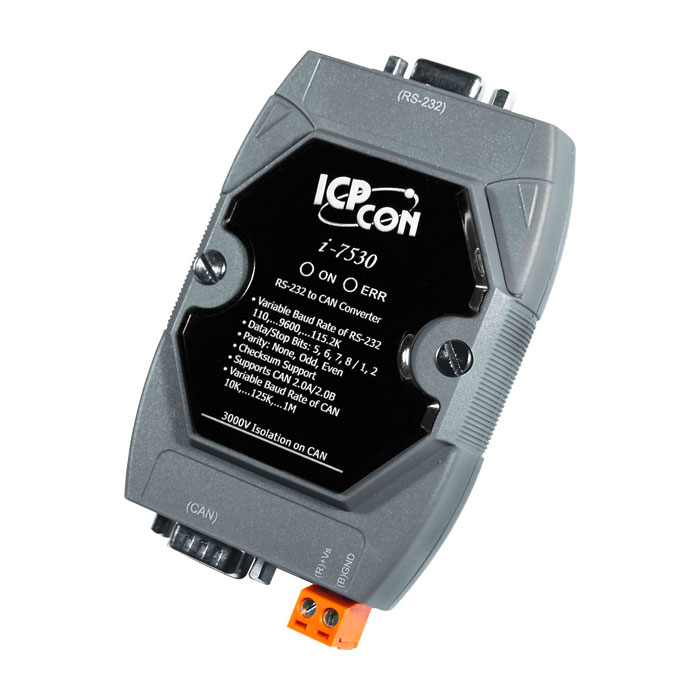
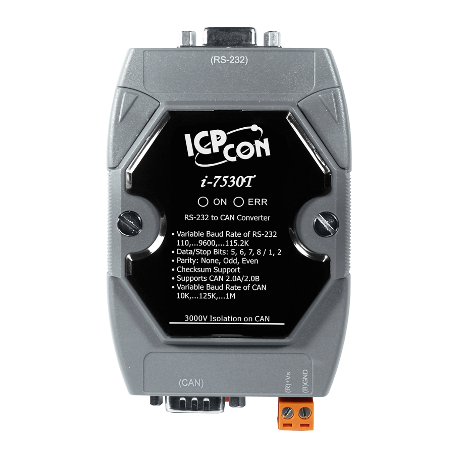
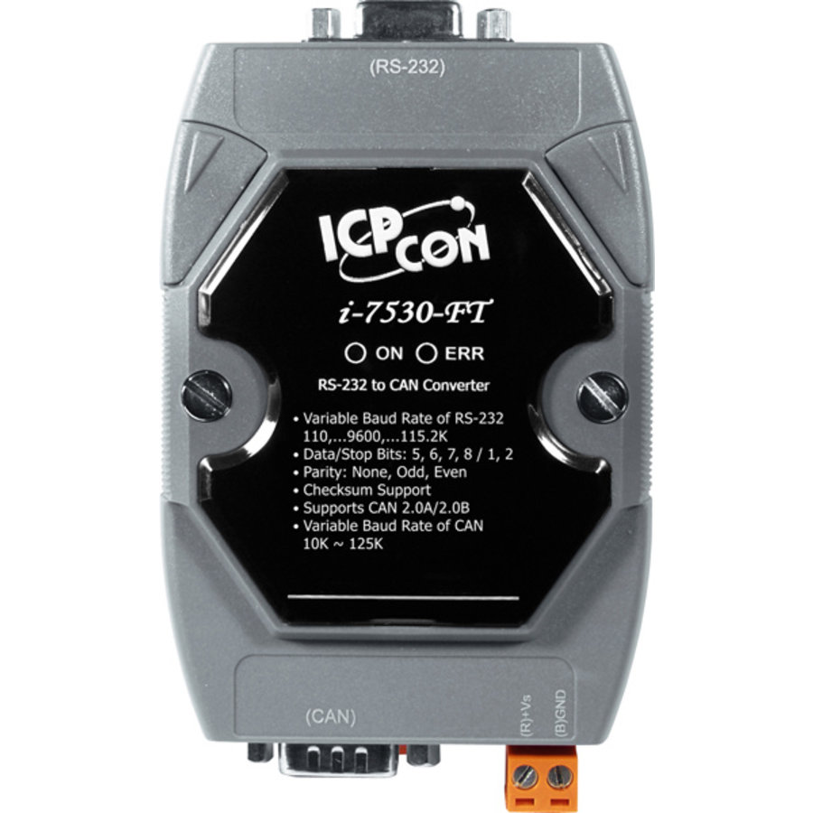
I-7530 / I-7530T / I-7530FT (RS-232 to CAN Converter)
|
|
CAN (Controller Area Network) is a serial bus system especially suited to structure intelligent industry devices networks and build smart automatic control systems. The following figure shows the application architecture for I-7530/I-7530T/I-7530FT modules. The PC can be the CAN host, monitor or HMI to access/control the CAN device through the CAN network by the I-7530/I-7530T/I-7530FT Converters. The programmable RS-232 device (For example: I-8411/I-8431/I-8811/I-8831/W-8031/W-8331/W-8731 embedded controller) can use the serial port to connect to the CAN network via the I-7530/I-7530T/I-7530FT modules. In order to use the CAN network with traditional RS-232 devices, we provide a way to achieve this purpose. The I-7530/I-7530T/I-7530FT are designed to unleash the power of CAN bus via RS-232 communication method. It accurately converts messages between CAN and RS-232 networks. This module let you to communicate with CAN devices easily from any PC or devices with RS-232 interface. |
Request For Quotation
Description

|
Moreover, we expand the functionalities of I-7530/I-7530T/I-7530FT for some special application. In pair connection mode, I-7530/I-7530T/I-7530FT can be used to connect PC with other RS-232 devices at the same time. The application architecture may be as follows. |

|
3000V isolation on CAN side (for I-7530/I-7530T) Watchdog inside Power and Error indicator display |
Applications
|
 |
|
|
|
|
|
Features
- Compatible with CAN specification 2.0A and 2.0B
- Fully compatible with ISO 11898-2 standard (for I-7530/I-7530T)
- Fully compatible with ISO 11898-3 standard (low speed fault tolerance) (for I-7530-FT)
- Support various baud rate from 10K bps to 1M bps
- Jumper for 120 Ω terminal resistor (for I-7530/I-7530T)
- Software configurable CAN and RS-232 communication parameters
- Power, data flow and error indicator for CAN and RS-232
- Watchdog inside
- Support transparent communication mode
- 1000 frames in CAN received buffer and 900 frames in RS-232 received buffer
- Full-duplex communication mode of RS-232 devices is not supported


